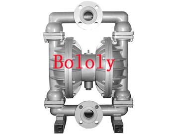
pneumatic diaphragm pumps use compressed air as power source for all kinds of corrosive liquid, with particles of liquid, high viscosity, volatile, flammable, poisonous liquid can be pumped exhaust, has been the formation of production, product quality is very popular. The main features of this pump is no irrigation water, pumping both liquid flow, but also conveying some of the easy flow of medium, high suction, adjustable head (0-50 m) air supply pressure is greater than 1kg only / cm2 that is able to work, absolutely fire and explosion, with a submersible pump, pump, impurities pump shield pump, mud pump capabilities, and transportation machinery of all the many features.
his four pneumatic diaphragm material: plastic, aluminum, cast iron, stainless steel. Diaphragm pumps were used depending on liquid medium nitrile rubber, neoprene, Viton, PTFE, poly ethylene forty-six. To meet the needs of different users. Placed in a variety of special occasions, for types of conventional pumps can not pump pumping the media, have achieved satisfactory results. The four pneumatic diaphragm material: plastic, aluminum, cast iron, stainless steel. Diaphragm pumps were used depending on liquid medium nitrile rubber, neoprene, Viton, PTFE, poly ethylene forty-six. To meet the needs of different users.
pneumatic diaphragm pump with a self-priming function, you can run empty, instead of a danger, you can dive work, conveying the fluid is extremely broad, from low viscosity to high viscosity, obtained from the corrosive viscous . No complicated control system, no cable, fuses, etc.. Small size, light weight, easy to move. So easy maintenance without lubrication, contamination will not drip as the working environment.
the current total of eight specifications Diameter: ¢ 10mm (3 / 8 "), ¢ 15mm (1 / 2"), ¢ 25mm (1 "), ¢ 40mm (1 1 / 2"), ¢ 50mm (2 "), ¢ 65mm (2 1 / 2"), ¢ 80mm (3 "), ¢ 100mm (4"). Three materials, aluminum, cast iron, stainless steel. Diaphragm according to the different liquid media were used nitrile rubber, chloroprene rubber, fluorine rubber, PTFE. To meet different user needs. The pump since production began, has been more than a thousand domestic petroleum, chemical, electronics, ceramics, textiles, paints, pharmaceuticals unit of the mechanical system used, placed in the kinds of special occasions, for a variety of conventional pumps can not pump pumping the media and the ideal replacement gear pump products are taken with satisfactory results.
main features of pneumatic diaphragm pumps:
1, no irrigation water, suction up to 7m, head up to 50m, the export pressure ≥ 6kgf/cm2;
2, flow spacious, and good performance, allowing by the maximum particle diameter of 10mm. Pumping slurry, impurities, little wear and tear on the pump;
3, head, flow through the valve opening to achieve stepless adjustment (pressure adjustment between the 1-7kgf/cm2);
4, The pump with no moving parts, no seals, diaphragm pumps will be pumping the media with moving parts, completely separated from the working medium, the transmission medium does not leak out. So pumping toxic, or corrosive media play, will not cause environmental pollution and danger to personal safety;
5, do not have electricity in flammable and explosive places safe and reliable;
6, can immersed in media work;
7, the role of convenient, reliable, open stop simply open and close the gas valve, even though no longer the case as an accident or sudden stop running medium, the pump will not result in damage, not once overload, the pump will automatically shut down, self-protection performance, when the load is back to normal, another automatically start running;
8, simple structure, less wearing parts, simple installation of the pump , easy maintenance, pumping will not come into contact with the medium valve, joint bars and other moving parts, unlike other types of pumps due to the rotor, piston, gear, blades and other parts of the gradual decline in performance wear and tear;
9, can transport more viscous liquid (viscosity of 10,000 cps in the following);
10, the pump without oil lubrication, even if idle, nor any effect on the pump, which is a major feature of the pump.
pneumatic diaphragm pump is mainly used for:
1, pump peanut butter, pickles, mashed potatoes, small sausage, jam, apple syrup, chocolate and so on.
2, pump paint, rubber, paint.
3, adhesives and glue, the pump can draw all types.
4, a variety of tile, porcelain, brick and pottery glaze.
5, wells drilled, the sediments with a pump and filling.
6, pumping of emulsion and fillers.
7, pumping of sewage.
8, with the pump for the tanker, barge warehouse clearance absorb water.
9, hops and yeast slurry, syrup, molasses.
10, pump shaft, tunnel, tunnels, mineral, slag in the water. Pumping cement grout and mortar. 11, all kinds of latex.
12, all kinds of abrasive, corrosive, oil and mud, grease and general cleaning containers.
13, a variety of toxic, flammable, volatile liquid.
14, various acids, alkalis, strong corrosive liquids.
15, a variety of high-temperature liquid-resistant up to 150 ℃.
16, as a variety of solid-liquid separation equipment pre-delivery pressure device.
pneumatic diaphragm pump performance parameters:
Model
Model 1 |
flow
Dischage
(m3 / h) |
head
Head
(m) |
outlet pressure
Exit
Pressure
(kgf/cm2) |
Suction
Sucked
lift
(m) |
maximum allowable particulate straight grain
Max grain D |
maximum supply pressure
Max
Pressure
(kgf/cm2) |
maximum air consumption
Max air
consumption
(m3/min) |
materials Materials |
aluminum
ZL104 |
stainless steel
1Cr18Ni9Ti |
iron
HT200 |
enhanced polypropylene
Enhanced
Polypropy lene |
| QBY-10 |
0 ~ 0.8 |
0 ~ 50 |
6 |
5 |
1 |
7 |
0.6 |
★ |
★ |
★ |
★ |
| QBY-15 |
0 ~ 1 |
0 ~ 50 |
6 |
5 |
1 |
7 |
0.3 |
★ |
★ |
★ |
★ |
| QBY-25 |
0 ~ 2.4 |
0 ~ 50 |
6 |
7 |
2.5 |
7 |
0.6 |
★ |
★ |
★ |
★ |
| QBY-40 |
0 ~ 8 |
0 ~ 50 |
6 |
7 |
4.5 |
7 |
0.6 |
★ |
★ |
★ |
★ |
| QBY-50 |
0 ~ 12 |
0 ~ 50 |
6 |
7 |
8 |
7 |
0.9 |
★ |
★ |
★ |
/ |
| QBY-65 |
0 ~ 16 |
0 ~ 50 |
6 |
7 |
8 |
7 |
0.9 |
★ |
★ |
★ |
/ |
| QBY-80 |
0 ~ 24 |
0 ~ 50 |
6 |
7 |
10 |
7 |
1.5 |
★ |
★ |
★ |
/ |
| QBY-100 |
0 ~ 30 |
0 ~ 50 |
6 |
7 |
10 |
7 |
1.5 |
★ |
★ |
★ |
/ |
pneumatic diaphragm pump works pneumatic diaphragm pump (PUMP DYNAMICS) pneumatic diaphragm pump is a positive displacement pump, pump-action explanation of the right of the figure shows the self-priming pump without the prior first pump-action of the flow pattern.
essed air through the valve
A's back into the diaphragm, squeeze the liquid from the diaphragm chamber. Such as air-driven piston-driven approach can avoid the mechanical stress generally, which significantly extend the life of the diaphragm. A compressed air will push the diaphragm away from the center of the body, the other side of the diaphragm B is linked at the same time pull to the center axis of the body, this time, the diaphragm B on the back of the air emissions from the exit to the pump body. Room B, so that the formation of a vacuum, which can rely on role of the outside air pressure will flow from the inlet manifold to push the ball away from the seat so that fluid can freely enter the chamber B until filled.
when squeezed by the air displacement of the diaphragm A reaches its limit, the air will be directed to the air valve of the back of the diaphragm B, the same pressure to form a push away from the crowded center of the body, while linked diaphragm A back to the center of the body, then the diaphragm B is driven by hydraulic pressure generated by pushing the ball back to the inlet valve seat, while pushing the ball away from the outlet valve seat so that fluid can be crushed and discharged from the export pump in vitro. A diaphragm is pulled back centrosome formation of this action so that A vacuum chamber, which can rely on atmospheric pressure to flow from the inlet manifold from the valve seat and push the ball into the A chamber until filled. When the diaphragm's movement is complete, the air valve again to guide the air to the back of the diaphragm A, and B to do air emissions diaphragm action. Start the pump back to the original state, the two diaphragm pump each completed an air emissions or emissions from the process fluid. This constitutes a cycle of the pumping process. According to usage, the pump pumping through several complete cycles to achieve self-priming pump action leaving the state.
a brief description of pneumatic diaphragm pumps:
two symmetrical pump working chamber, each equipped with a flexible diaphragm, diaphragm-bar linkage will be a blend of two compressed air from the pump inlet head After entering with the valve, push the two working chamber of the diaphragm, joins the two-bar linkage driven diaphragm synchronous movement. At the same time, the other working chamber of the gas discharged from the pump outside the back of the diaphragm. Once at the end of travel. Valve is automatically compressed air into the other working chamber, push the diaphragm in the opposite direction, thus forming two synchronized reciprocating motion of the diaphragm. Each working chamber there are two one-way valve is set, diaphragm reciprocating motion, resulting in changes in the working chamber volume, forcing the two-way ball valves alternately open and close, so the liquid continuous suction and discharge.
pneumatic diaphragm pump installation dimensions table:
Model
Model |
A |
B |
C |
D |
E |
H1 |
H2 |
H3 |
H |
Threaded
Screw |
flange
Flange |
| NPT / RC |
D1 |
D2 |
D3 |
D |
n |
d |
| QBY-10 |
135 |
48> |
218 |
144 |
12 |
34 |
176 |
10 |
226 |
1 / 2 |
- |
- |
- |
- |
- |
- |
| QBY-15 |
135 |
48 |
218 |
144 |
12 |
34 |
176 |
10 |
226 |
1 / 2 |
- |
- |
- |
- |
- |
- |
| QBY-25 |
236 |
145 |
381 |
248 |
12 |
46 |
344 |
18 |
412 |
1 |
- |
- |
- |
- |
- |
- |
| QBY-40 |
236 |
145 |
381 |
248 |
12 |
50 |
348 |
18 |
428 |
11 / 2 |
- |
- |
- |
- |
- |
- |
| QBY-50 |
320 |
220 |
518 |
347 |
14 |
50 |
521 |
27 |
609 |
2 |
84 |
50 |
125 |
165 |
4 |
18 |
| QBY-65 |
320 |
220 |
518 |
347 |
14 |
50 |
521 |
27 |
609 |
21 / 2 |
104 |
65 |
145 |
185 |
4 |
18 |
| QBY-80 |
360 |
240 |
634 |
455 |
18 |
96 |
696 |
50 |
842 |
3 |
118 |
80 |
160 |
200 |
8 |
18 |
| QB-100 |
360 |
240 |
634 |
455 |
18 |
130 |
721 |
60 |
960 |
- |
140 |
100 |
180 |
200 |
8 |
18 |